Wireless LAN basics
Wireless LAN Basics
Wireless Frequencies
The IEEE 802.11b and 802.11g standards define a single range of radio frequencies from 2.412GHz to 2.472GHz that are to be used for wireless network transmissions. Within this range, thirteen frequencies are defined as channels, numbered from 1 to 13, with each channel separated from the next by a difference of 5MHz. Unfortunately the characteristics of radio transmitters mean that the signal for each channel is in fact 25MHz wide, so that the channels overlap. As shown in Figure 1, to avoid overlapping signals interfering with one another it is necessary to use channels that are at least five apart. Figure 1 shows that channels 1 and 6 can be used together without overlap, but they cannot be used at the same time as channels 2, 3, 4 or 5.

Figure 1: Effect of Wireless Channel Overlap.
If two access points transmit signals from the same or overlapping channels into the same area then their signals are likely to interfere, resulting in poor and unreliable reception. In practice this means that only three different channels can be used in any given area. The channels typically used are 1, 6 and 11. Channels 12 and 13 are not used in the USA so many laptops and other wireless devices will not recognise them. A Cisco® technical note has details of the radio spectrum used and the signals seen by users in overlap areas (see Reference 1).
The IEEE 802.11a standard uses a different range of frequencies around 5GHz but allows for eight to twelve non-overlapping channels, depending on country and product. Channel identifiers run from 34 to 64. To avoid overlaps in an 802.11a network, channels should be allocated that are at least four apart. Allocating channels for an 802.11a network should therefore be much easier than for 802.11b or 802.11g.
The restriction on channels applies to access points covering the same area, but also to access points covering adjacent areas. If the aim is to have complete wireless coverage throughout a building by providing multiple access points, then there will inevitably be places that receive signals from two or more access points. To avoid channel overlaps causing a poor signal in these areas, the access points must use different channels, again separated by at least five channel numbers (or four for 802.11a). Planning which access point uses which channel therefore becomes a map colouring exercise, with the requirement that no two adjacent areas are the same colour and, for 802.11b or 802.11g, that only three colours are available. As shown in Figure 2, if access points were placed in a regular grid with perfect transmission of radio signals from all of them, then three channels would be sufficient to cover an area with no overlaps. However, this ideal situation is only likely to be realised on a flat playing field, and certainly not inside a building where walls and furniture are likely to distort the areas of coverage and limit where access points can be located. Mathematical theory says that in some circumstances four different colours are needed to colour a map, so an ideal allocation of 802.11b or 802.11g channels may be impossible. In these cases it will be necessary to compromise on either coverage or performance.
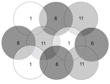
Figure 2: Ideal Theoretical Allocation of Three Channels.
To obtain consistent performance from a wireless network, each access point should be fixed to transmit on a single, pre-defined channel. Some types of access point offer a simple installation mode where the access point will choose a channel itself based on the other signals present.
However, this does not allow for human considerations such as areas where good performance is particularly important. The behaviour of such systems when new access points appear is also very uncertain. Automatic selection of wireless channel is therefore best avoided.
Fortunately it is only the access points that need to be configured to use a particular radio channel. Laptops and other wireless client devices will normally look for transmissions on all frequencies and select one without needing manual configuration.
Signal Strength
Like any radio or sound signal, a wireless network transmission gets ‘quieter’ the further you are located from the transmitter. The ‘loudness’ of the signal is measured as signal strength relative to some reference signal: for wireless LANs this reference level is usually 1 milliwatt. Because sensitive wireless cards can receive and use a signal that is a minute fraction of the strength at the access point, the logarithm of the ratio is usually quoted, rather than writing very long decimal fractions. The resulting values, in units of decibel milliwatts (dBm), can look strange at fi rst, but with practice they are easy to deal with. Positive values mean the signal is stronger than the reference level; negative values mean it is weaker. A 1 milliwatt signal therefore corresponds to a value of 0dBm; the weakest signal that can be used by a typical IEEE 802.11g laptop card is -94dBm, but at this level the maximum data rate will only be 1Mbit/s. As the signal strength increases, so does the possible data rate, with the theoretical maximum of 54Mbit/s for IEE 802.11g achieved by the same card at a signal strength of -71dBm (corresponding to about 200 times stronger than the minimum signal).
Signal strength decreases as distance from the transmitter increases, and hence so do data rate and sensitivity to noise. In the open air the signal strength from a normal 802.11g access point will usually drop to unusable levels at a distance of about 100m, with the data rate decreasing at distances more than about 30m from the access point (indoors these ranges are likely to be reduced by at least 20%). Typical bandwidths available at different ranges from an 802.11b/g access point are shown in Figure 3.

Figure 3: Signal Strength versus Distance from Access Point.
If there are materials other than air between the transmitter and the receiver (walls, ceilings, windows or even people or piles of paper) then these will reduce the signal strength much more quickly and hence reduce the effective range. A table of different materials and their effect on wireless network signals is available from Intel (see Reference 2).
The power of wireless transmitters is limited by law, so it is not possible to increase signal strength simply by increasing the transmitter power. However, it may be possible to address particular problem areas by using a directional aerial to concentrate the signal. Different types and positions of aerials on receiving equipment may also result in one client receiving a stronger signal than another. Laptops with receiving aerials built into a screen, and therefore perpendicular to the signal, are likely to perform better in areas of low-strength signals than those that use a PCMCIA card where the aerial is likely to be close to a human or desk that will be absorbing the signal. Client aerial differences are more likely to provide an indication of a problem than a solution to it: if an area suffers from low signal strength then the only permanent solution is to install another access point.
Noise
Not all radio transmissions are generated by access points, and those that come from other sources may sometimes drown out the wireless network signal. Radio frequency noise is therefore another area that should be checked during a wireless survey. Both the 2.4GHz band used by 802.11b and 802.11g and the 5GHz band used by 802.11a are unlicensed so many different types of equipment may transmit in these frequencies, either accidentally or deliberately. Other types of radio transmitter using the 2.4GHz band include cordless telephones and Bluetooth devices, while microwave ovens, RF lights and other electrical devices may also generate noise as a side effect of their operation. At present there is less competition for frequencies in the 5GHz band used by 802.11a networks but this situation is likely to change as other devices move into that frequency band.
Noise may also be generated by wireless networks themselves if their signals are damaged by the environment so as to become unusable. The most common cause of a wireless transmission being reduced to nonsense is multi-path reception, where a signal reaches the receiver by different routes (for example because it is reflected off a concrete wall) and interferes with itself. It has also been reported that panels of wire-reinforced glass in swinging doors can cause serious noise problems as they cause a rapidly changing diffraction pattern in the signal, while passing traffic outside a wall appeared to generate a rapidly changing pattern of reflections that reduced network performance.
The level of radio frequency noise in an area is measured in the same way as the signal strength, and with the same reference level, so is also recorded in dBm.
Signal/Noise Ratio
Obviously, if there is a high level of background noise then a higher signal strength will be needed. A particularly useful measure for identifying problems in a radio environment is therefore the difference between the wanted signal and the unwanted noise. No matter how strong the signal, if it is drowned out by a similar level of noise then the performance of the wireless network will be poor. Since the values used to measure signal and noise strength are logarithms, simply subtracting the noise level from the signal strength gives the signal/noise ratio. If the signal level is less than 10dB higher than the noise level (corresponding to noise a tenth as loud as the signal), then the data rate and the reliability of the wireless network are likely to be significantly reduced.
Although dBm are the correct engineering units to use to measure radio signal and noise levels, different wireless LAN devices may use other scales in an attempt to be more userfriendly. However these rarely give as much information as a dBm value. Web sites suggesting how to interpret these values are listed in References 3 and 4.


