IPSec implementation and worked examples
This chapter shows how the facilities provided by IPSec can be used in practice to create secure VPNs. The examples use Cisco® routers and Windows® 2000/XP workstations. These devices have been chosen because they are widely used and most readers will have access to hardware similar to that discussed in the examples. Two common requirements are discussed: providing a secure VPN tunnel between two private networks, for example a remote site or office and a main campus, and providing a secure remote access service for staff working at home.
A VPN must be prepared in advance by defining its policy and the security technologies it will support. Each participant in a VPN has its own set of policies and technologies, described in an SPD. The policies in the SPD define what traffic should be secured and how that security should be applied. For example the policy may define certain characteristics, such as source and destination addresses, that require encryption and/or authentication. In this way IPSec processing may be restricted to certain packets only. The technologies part of the SPD defines what protocols and algorithms the device will offer to its peer during the negotiation phase, both for authentication and encryption.
When a VPN connection is created, the end points negotiate on the basis of their own SPDs and, provided agreement can be reached, an SA is created that defines the connection. If the peers cannot agree a set of technologies, for example because there are no encryption algorithms supported by both ends or because the digital signature offered as proof of identity by one peer is considered too weak by the other, then the VPN will not be established.
Configuring IPSec on Cisco® Routers
The Cisco® IOS is not generally supplied with IPSec as it is a chargeable option. An approved vendor’s pre-sales advice should always be sought before purchasing any new equipment. Specifying the 3DES version of the ‘Firewall’ Feature Pack should ensure that new equipment has full support for IPSec pre-installed. Installing IPSec functionality also requires additional flash and working memory and consideration should be given to providing sufficient processing power. Any router that is required to perform a lot of IPSec should be fitted with a hardware accelerator module so that the main processor does not become overloaded.
Configuring IPSec on a Cisco® device comprises the four stages that are outlined below. In the interests of brevity and pertinence, this document does not discuss any subsidiary Cisco® technologies such as Access Control Lists (ACLs) or the general operation of Cisco®’s command-line IOS.
Configure Crypto Lists
The router must be configured with an ACL that specifies the traffic that should be subject to IPSec processing. This may be of the usual standard or extended types. If the former, then only the source address is matched while extended lists can match the protocol and source and destination addresses. In this context, a ‘permit’ statement in the ACL means that the matching packets should undergo IPSec processing. It is the author’s opinion that crypto lists should not contain any ‘deny’ statements, althoughthe router will process such lines. The implicit denial at the end of a list should be sufficient for almost all cases.
Configure Transform Sets
The router is configured with the set of protocols and algorithms that it will offer to a peer during negotiation of the IPSec SAs. The protocols will be either AH or ESP and the algorithms refer to the encryption and one-way hash functions to be used in conjunction with the selected protocol(s). The desired IPSec mode must also be selected here, the default being tunnelling.
Apply Crypto Maps
The two preceding tasks define what traffic the IPSec kernel should process and how that processing should be performed. These two strands are drawn together as a named policy called a crypto map that must be bound to the relevant egress interface. Any traffic leaving this interface will be checked against the relevant crypto list to determine whether it should be passed to the IPSec kernel for encapsulation before leaving the interface.
Configure Key Exchange Policies
An IKE policy must be configured so that the router is aware of how to authenticate the remote peer and how to conduct the key exchange. The variables comprise the encryption and hashing algorithms, the authentication method and the Diffie-Hellman group identifier.
This recipe is a general overview of the necessary stages in configuring Cisco®’s implementation of IPSec. There are many subtleties and additional techniques some of which, such as dynamic crypto maps, are demonstrated in the examples in Sections 7.3 and 7.4. The interested reader should consult the official Cisco® documentation for a complete and authoritative discussion.
Configuring IPSec on Windows® 2000/XP
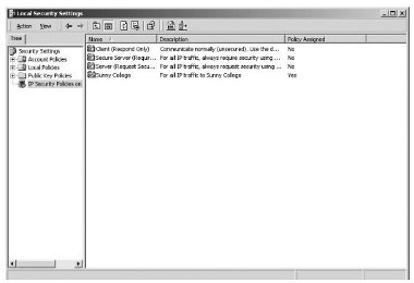
All versions of Microsoft® Windows® 2000 are supplied with a full implementation of IPSec. The Microsoft® Management Console provides a snap-in called ‘IP Security Policy Management’ through which all aspects of IPSec may be controlled by constructing and applying policies. Access to this interface is most readily obtained by running a program called ‘secpol.msc’ and selecting the ‘IP Security Policies on Local Machine’ node.In the screen shot above there are four IPSec policies, three of which are pre-installed but are not active. The fourth policy, called ‘Sunny College’, has been assigned and is therefore actively processing traffic.
Double-clicking a policy in the right-hand list view displays a properties page listing the rules that comprise the policy.
Screenshot printed by permission of Microsoft Corporation
Double-clicking a rule in the policy’s properties page displays all of its characteristics. A rule is composed of a filter list, a filter action, an authentication method and an optional tunnel setting, which is not required for transport-mode IPSec.

Screenshot printed by permission of Microsoft Corporation
Filter Lists
Multiple filters may be combined to create a filter list that specifies which traffic should be protected by the IPSec policy. These filter lists are equivalent to Cisco®’s extended ACLs in that source and destination addresses or subnets may be specified as well as the IP protocol and, where appropriate, port number.
Some traffic is automatically exempted from IPSec regardless of the filter lists. Firstly, only unicast traffic may be secured. Any packet sent to a broadcast or multicast address will be unprotected. This is to be expected as IPSec requires SAs to be negotiated between two peer stations before any secured packets may be transmitted. By definition, a sender does not know the identity of receiving stations when transmitting to broadcast or multicast addresses. Any IKE-related traffic on the ISAKMP port (UDP/500) will not be secured because this traffic is concerned with negotiating IPSec SAs.
Kerberos traffic (UDP/88) is also exempted from IPSec processing on Windows®. Unlike the other exemptions, this is not a consequence of the IPSec paradigm. Kerberos is the security protocol used during authentication against a Windows® 2000/XP user database. If tunnel mode IPSec is required to relay packets between a remote Windows® client and a domain controller, then any authentication traffic generated by the client will never reach the server because the IPSec exemption prevents the packets from proceeding via the tunnel. A modification to the Windows® registry suppresses this behaviour. The registry editor should be used to locate the following key:
HKEY_LOCAL_MACHINE\SYSTEM\CurrentControlSet\Services\IPSEC
The following value should be added to this key:
Value Name: NoDefaultExempt Data Type: REG_DWORD Value: 1
Once the machine has rebooted, this value will take effect. Windows® authentication will fail over an IPSec tunnel if this value is absent.
Screenshot printed by permission of Microsoft Corporation
Filter Actions
Having decided what traffic should be protected by means of a filter list, the policy must specify the desired combination of algorithms and IPSec protocols. Either AH or ESP may be selected along with the appropriate hashing algorithm and, in the case of ESP, either the DES or 3DES encryption algorithms.
Authentication Methods
The preferred authentication method is to use a certificate, which is selected by specifying the relevant CA’s self-signed ‘trusted root’ certificate. If the shared secret method is preferred then a new registry value must be added to suppress the automatic filter that enforces CA authentication. The registry editor should be used to locate the following key:
HKEY_LOCAL_MACHINE\System\CurrentControlSet\Services\Rasman\ Parameters
The following value should be added to this key:
Value Name: ProhibitIpSec Data Type: REG_DWORD Value: 1
Once the machine has rebooted, this new value will take effect. Shared secret authentication will fail if this registry value is absent.
Tunnel Setting
For tunnelling mode IPSec, two rules are required, one for the outbound traffic and a second for the inbound. This is because only a single tunnel endpoint may be specified within a rule and so a rule is required for each end of the tunnel. From the perspective of one peer, one rule will apply to inbound traffic as the tunnel endpoint will be itself and the other rule will apply to outbound traffic with the tunnel endpoint being the remote peer.
Configuring an IPSec-Protected GRE Tunnel
Consider two sites, each with networks operating on shared-media Ethernet and a range of private IP addresses (see the diagram in Section 6.2.1). A Cisco® router performing Network Address Translation (NAT) provides Internet connectivity via an E1 (2 Mbit/s) leased-line connection to an ISP. Suppose the two sites wish to communicate using their existing external connectivity. One solution would be to create NAT mappings within each router’s configuration so that every station that needs to be visible to the remote network can be reached by means of a public IP address.
This arrangement is undesirable on three counts:
- increased consumption of public IP addresses may limit the number of machines that can be made reachable
- machines that had been secure from ill-intentioned crackers on the Internet by virtue of running on private address space have now been exposed, and although traffic filters on the router might reduce the risks, mistakes in their construction could still allow an intruder some form of access
- the traffic between the sites may be of a confidential nature and should not be transmitted over an insecure medium such as the Internet without first authenticating and encrypting the packets.
At first glance, IPSec in tunnel mode appears to be the ideal solution, but in this instance it will not work because any traffic entering the router from the internal network will be operated upon by the NAT first, and the source address changed. Therefore, the crypto will never be triggered. By routing any traffic to the remote site through a ‘Tunnel’ interface, the packets will not be operated upon by NAT. If a crypto map is bound to the tunnel interface then IPSec protection will also be afforded to any traffic leaving via the tunnel. In this case, the tunnel is established by means of the initial GRE encapsulation and so it is appropriate for IPSec to run in transport mode. Relevant excerpts from the configuration of one of the routers are given in Figure 11.

Figure 11. Excerpts from router configuration for configuring an IPSec-protected GRE tunnel.
When the router receives a packet with the destination address in the 192.168.100.0/24 range, the following sequence of events takes place:
- the router learns from its routing table that the packet should be sent via the Tunnel0 interface
- the packet enters the tunnel interface, and a GRE and a new IP header are prepended
- because a crypto map has been bound to the tunnel interface, the tunnelled packet is diverted to the IPSec kernel and is not immediately dispatched via the serial interface
- if a suitable IPSec SA is not present, the router commences IKE negotiations with the peer (whose IP address is known from the router configuration)
- once an SA has been established, an ESP header is inserted between the outer IP header and the GRE-header
- the IPSec kernel has completed its processing and so the heavily encapsulated packet is free to proceed to the IPSec peer router by way of the serial interface.
Once GRE encapsulation has been completed, the packet’s source and destination addresses will be 193.61.71.246 and 194.83.103.186 respectively. The NAT is configured only to trigger for packets with a source address in the 192.168.17.0/24 range, and so any packets routed through the tunnel interface are shielded from the NAT process.
One subtle consequence of combining transport-mode IPSec with GRE tunnelling is that large packets may be subjected to two fragmentations within the same router before transmission through the serial interface. This is clearly undesirable as it consumes processor cycles on both the source and destination routers and wastes buffer memory and bandwidth. Assuming that the Maximum Transmission Unit (MTU) of both the internal (Ethernet) and external (serial) interfaces of the router is 1500 bytes, then fragmentation of packets of this size can occur following both the GRE and IPSec encapsulations. By reducing the MTU of the tunnel interface to a specific lower value (as shown in the example configuration) packets are fragmented only once after GRE encapsulation with sufficient clearance to accommodate the ESP encapsulation without the need for a second fragmentation.
Configuring Tunnel Mode IPSec
With the advent of affordable home broadband based on ADSL technology, it is worth investigating whether this type of connectivity could be used to provide secure remote access to an organisation’s network. By employing IPSec tunnelling with a Windows® 2000 workstation at the home end and a Cisco® router at the office end of the tunnel, a remote user can transparently access the office network. The router is configured with ‘dynamic’ crypto maps in which it is not necessary to specify the IP addresses of the peers ahead of time in the router’s configuration. This means that remote users whose ISP assigns IP addresses dynamically can still establish properly authenticated tunnels with the router.
The router configuration is simpler than in the previous example as much of the complexity has been moved to the remote users’ Windows® 2000 workstations. The college servers are all located on the privately numbered 192.168.17.0/24 network and so the remote user must tunnel IPSec-secured packets through to this range of addresses. Relevant excerpts from the router configuration are shown in Figure 12.
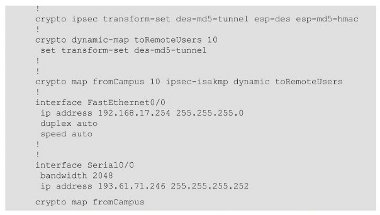
Figure 12. Router configuration for configuring tunnel mode IPSec.
A dynamic crypto map acts as a template for ephemeral crypto maps that are constructed by the router itself when a remote peer initiates a connection. The peer’s IP address and a matching crypto list cannot be configured in advance as these contributions to the crypto map can only be known at run-time. Because it is just a template, a dynamic crypto map cannot be directly bound to an interface. Instead it is associated with a crypto map, which is bound to the interface, as shown in the configuration.
The tunnel will always be initiated from the remote workstation, and so the rules specifying which packets IPSec should process are located on this peer. As discussed previously, the IPSec policy comprises two separate rules, one for outbound and another for inbound traffic. Each rule’s filter list comprises just one entry; the filter for the outbound rule is shown below.
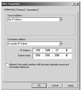
Screenshot printed by permission of Microsoft Corporation
In this example, a specific IP address has not been used as the filter’s source. This is necessary if the remote workstation obtains its IP address dynamically. Suppose, however, that college staff have been issued with notebook computers that can be used either from home or directly connected to the college network. When used remotely, traffic to machines on the college network must proceed via a secure tunnel. When the notebook is used at the college, the IPSec policy should be suppressed. Providing the ISP supplies statically assigned IP addresses, by specifying this address as the outbound rule’s source, the IPSec policy will not interfere with the correct operation of the notebook when it is connected to the LAN.
Three security methods (high, medium and custom) are available for the filter action. The first corresponds to ESP with the DES encryption algorithm and the second corresponds to AH. If the ‘Custom Security Method’ is selected then all the parameters affecting encryption and authentication may be modified. It is even possible to apply both AH and ESP, but this does not offer any significant benefits.
In the screen shot below, the ‘Custom Security Method’ has been selected and the more secure 3DES algorithm has been chosen as the encryption algorithm. The filter action may comprise a number of different such methods, in which case the workstation will negotiate one of the configured methods with the peer router.
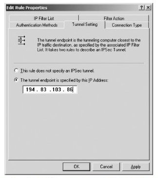
For tunnel mode IPSec, the identities of both ends of the tunnel must be specified. Each of the two rules (outbound and inbound) corresponds to opposite ends of the tunnel. The tunnel endpoint for the inbound rule will invariably be the workstation itself, and for the outbound rule it will be the IP address of the remote peer. The tunnel setting for the outbound rule is shown below.

Screenshot printed by permission of Microsoft Corporation
The IPSec policy is complete once an authentication method has been selected. This may be Kerberos (generally only suitable when both endpoints are Windows® devices), a pre-configured shared secret or a certificate. If certificates are not to be used, the reader’s attention is drawn to the advice in Section 7.2.3.
Screenshot printed by permission of Microsoft Corporation


