Firewall location and configuration
Design
The perimeter of an organisation’s LAN is the obvious place to locate its security protection. However, the perimeter has moved: no longer is there just one ingress to a LAN, but many points of access. Wireless networks, modems, secondary Internet connections and the migration of laptops between networks mean the boundary is constantly moving.
Moreover, it is critical to ensure that new or updated firewalls will be future-proof. The increase in network bandwidth available has been significant in recent years and is stretching firewall resources. Firewalls need to be able to manage the maximum available upstream bandwidth, otherwise a DoS attack could result in firewall failure.
Isolating networks
Logically, networks are already isolated by the netblocks that define them. To enable communication, routing protocols allow traffic between configured netblocks. However, do these netblocks need full connectivity with each other?

Figure 5: The spread of infection on a campus LAN
Malicious code — worms in particular — can propagate through many different attack vectors. One of the more common is the Microsoft Windows® NetBIOS/SMB/CIFS.
Attacks taking advantage of insecure NetBIOS/SMB/CIFS fileshares and vulnerabilities in the underlying code are a common cause of swift spreading LAN-based infections. A good form of defence against this is to block these protocols from LANs where not required. The ports TCP/UDP 137, 138, 139 and TCP 445 can be blocked between LAN segments to isolate individual networks from attack. If a computer is compromised by a worm in one segment, only other vulnerable computers on that segment are compromised. However, when core file, print and AD authentication is required, then these protocols will have to be allowed to the network where the servers are located.
With the increased volume of different attack vectors against varying software, the implementation of a default deny policy between networks is becoming common, with exceptions set to allow desired services to operate.
Isolating different classes of users
Different classes of users often require different levels of access to IT systems. Many organisations already separate student and staff networks. The practice is very sensible, as it provides another layer of defence. However, a problem occurs when student and staff traffic meets in open access areas or on wireless networks. It is good policy to allow access to specific information systems only from wired staff networks.
Isolation can be achieved using VLAN technology which is already common on most organisational networks. Many VLANs can exist on a network at the same time, although there are limits on some vendors’ hardware.
VLANs allow networks to be separated so that different policies can be assigned to each. There are additional benefits from a networking perspective, including a reduction in broadcast domain sizes and easier administration.
802.1Q trunking provides a method for multiple VLANs to be fed to networking devices. VLANs are tagged with IDs for differentiation with ID 1 reserved for the default untagged traffic. Most vendors use the 802.1Q standard, except for 3Com®, who use Virtual LAN Trunk. Cisco historically used Inter-Switch Link, but this is now deprecated over 802.1Q. However, security measures which rely on VLANs are not entirely dependable because of the technique of VLAN Hopping. This involves changing the VLAN ID tag on encapsulated packets in a VLAN trunk, but this is not easy to execute on a production network.

Figure 6: Use of VLANs to separate network traffic
Demilitarised Zone
A DMZ describes a network in which the host servers are located. Limited connections from the Internet are allowed into the DMZ to provide services like web (HTTP) access and e-mail (SMTP et al). Connections from the DMZ to the internal network are not usually allowed by default, which protects the computers inside from compromised hosts in the DMZ.
Hosts in the DMZ are frequently additionally protected using NAT or PAT to further obfuscate the networking configuration.
A DMZ is often implemented using a third physical interface on the firewall, but an alternative is to use two firewalls in series with the DMZ. This provides an additional level of protection for the internal network.
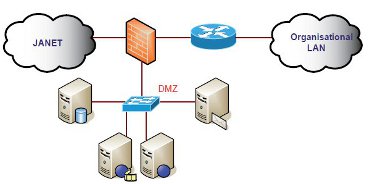
Figure 7: Organisational Demilitarised Zone implementation
Protecting Sensitive Information Systems
Some computer systems on any network are more critical than others. Computers which store sensitive information present a higher risk because of their attractiveness for attack and its subsequent impact. Sensitive information systems can be protected by a number of different methods and using a combination of these provides defence in depth and enhances overall security.
Host security
It is important to ensure computers are built and maintained in a secure manner to prevent intrusion through operating system and configuration vulnerabilities. There are a number of steps that can be taken to secure an operating system, from the most basic at installation stage to more granular changes post-configuration.
It is good practice to ensure the computer is either disconnected from the network entirely or connected to a heavily firewalled development network at build time. Operating systems are often far from secure during installation and being connected to the production network would leave the computer vulnerable. To reduce the risk of a DoS attack, different disk partitions for system volume, user storage, individual services and logs is ideal. It is also worth considering whether all the services enabled are actually required: does IIS or Apache need to be running on all computers?
Post-installation it is essential that all operating system and service patches are applied. This needs to be achieved securely, not via an unprotected network. Anti-virus software needs to be installed, along with the patch management software such as yum, smpatch, Windows® automatic updates, SUS or WSUS.
Once the machine has been configured, all ACLs and permissions set, and all logging and auditing enabled, it is wise to create a machine baseline snapshot. This will give a standard to compare the computer against should it begin to behave differently. It will make it easier to identify additional open ports or CPU-intensive processes.
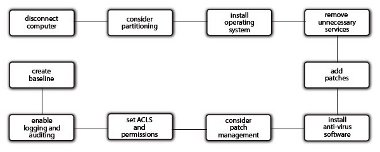
Figure 8: Host security implementation plan
Isolation
Increasingly, information systems are isolated from other systems. This can take the form of dedicated VLANs, small netblocks per system groups, NAT, PAT, router ACLs or additional firewalls.
When a system is isolated, the traffic both into and out of the system is restricted which means the system is more difficult to compromise. If the system does get compromised then spread is significantly reduced.
Firewalls
Firewalls installed specifically to protect information systems can provide another layer of protection and dedicated rules. It is recommended that, if possible, two different hardware vendors are used to provide security against vulnerabilities in the firewall code.
The firewall could be host-based or network-based, although it is worth remembering that host-based firewalls are typically inferior. They are inflexible and often fail open, as opposed to network-based firewalls which fail closed.
Protecting a number of machines with a variety of requirements behind a firewall can be achieved with virtual firewalls or different contexts.
Network ACLs
An alternative to a fully functioning firewall is to protect information systems using network ACLs. Network ACLs can be implemented on routers or on some network switches. With Cisco Enhanced Images, network ACLs can be implemented on incoming traffic.
Access lists provide the flexibility to filter packets at both ingress and egress of network interfaces, according to IP address, protocol and application.
Secure communications
Even with modern packet-switched Ethernet, there is still a possibility that communications traffic can be sniffed. For example, tools like macof can be used to turn switches into hubs if they are not suitably protected. Secure communications can also be used to prevent antireplay and man-in-the-middle attacks.
All authentication and other sensitive data should be secured. If the protocol being used
does not support secure encryption, then an SSL tunnel can be employed.
Physical Interfaces
All firewalls will have a number of interfaces which can be physical or virtual (or sub). Physical interfaces are where actual cables are connected to attach the firewall to the network infrastructure. All firewalls must have a minimum of two physical interfaces for normal operation, but this is not a limit. Interfaces for DMZ, management and failover all present configuration options.
Virtual interfaces are used when there are fewer physical interfaces available than required, or to support VLANs and/or virtual firewalls/contexts. Virtual interfaces split a physical interface into separate interfaces depending on the 802.1Q trunk. It is recommended that at least the primary firewall for an organisation has physical inside, outside and DMZ (if appropriate) interfaces, as they are, by their nature, more secure than virtual ones.
Failover
The provision of failover is a key issue in firewall implementation as fault tolerance needs to be a priority within the network infrastructure.
Failover can be implemented in two ways traditionally: Active/Active and Active/Passive. With the Active/Active method, two firewalls run concurrently, sharing the traffic to provide failover should one fail.

Figure 9: Firewalls in an Active/Active failover operation
With Active/Passive failover, two firewalls run concurrently, but traffic is only handled by one. When failure occurs, the other firewall takes over.
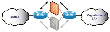
Figure 10: Firewalls in an Active/Passive failover operation
Multiple contexts can be used to create numerous virtual firewalls with different configurations on the same piece of hardware. This enables two devices to balance the load and provide fault tolerance.
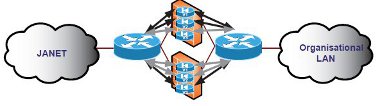
Figure 11: Firewalls configured for Active/Active failover operation and load balancing using multiple contexts
Router ACLs and CBAC
Router ACLs were the first protection technology implemented by organisations. However, they can increase resource usage and CPU overhead. Dedicated firewalls are more flexible and can provide better fault tolerance. Router ACLs should only be used to isolate netblocks and implement limited rules. Core Cisco chassis-based routers can offload firewall features using a FWSM which can provide 1,000 virtual firewalls per installation.
CBAC is a Cisco IOS option for existing routers which monitors packets and implements a Layer 3 stateful inspection. This is a good solution for small installations.
CBAC also provides DoS protection and enforces timeout and threshold controls. This includes restricting the total number of half-open sessions and rules based on time scales and hosts.
When a packet is received at an interface it is evaluated against the existing outbound access list, and may be permitted to pass. (A denied packet would simply be dropped at this point.) The packet is then inspected by CBAC to determine the state of the packet’s connection. This information is recorded in a new state table entry created for the new connection.
Based on the state information, CBAC creates a temporary access list entry which is inserted at the beginning of the external interface’s inbound extended access list. This entry is designed to permit inbound packets that are part of the same connection as the outbound packet just inspected. The outbound packet is then forwarded out of the interface.
Later, an inbound packet reaches the interface which is part of the same connection established with the outbound packet. The inbound packet is evaluated against the inbound access list, and is permitted because of the temporary access list entry previously created. The inbound packet is then inspected by CBAC, and the connection’s state table entry is updated as necessary. On the basis of the updated information, the inbound extended access list temporary entries might be modified in order to permit only packets that are valid for the current state of the connection.
Any additional inbound or outbound packets that belong to the same connection are inspected to update the state table entry and to modify the temporary inbound access list entries as required.
When the connection terminates or times out, the connection’s state table entry is deleted and the temporary inbound access list entries are deleted.
Policy Based Routing
PBR is used to enable routers to make decisions on where to route traffic according to policies configured on the device. This can divert traffic around a firewall or ensure it always goes through it.
With backup traffic, it can be useful to ensure that it is diverted around a firewall rather than overwhelming it. A rule can be constructed to identify traffic between a source network and backup machines on particular ports. When a router sees a match for this traffic, it is directed to a particular netblock instead of using the routing table to identify an appropriate entry.
PBR is very flexible and can match packets on not only addresses but ports, protocols and packet size. PBR can also be used to provide cut-through routing between a private network and an organisational network where traffic would usually need to traverse the public Internet.

Figure 12: Policy Based Routing used to route backup traffic
Operational Modes
Firewalls can be configured to operate in a number of different modes and some can even operate in multiple virtual modes.
In routed mode, the firewall acts as a router deciding where traffic should go and whether it should traverse the firewall. If the addresses on the inside interfaces are not Internet-facing, then the firewall will have to use NAT or PAT to translate the traffic.
Network Address Translation
NAT allows a single device, such as a router, to act as an agent between the Internet (or ‘public network’) and a local (or ‘private’) network. This means that either a single or a pool of Internet IP addresses is required to represent an entire group of computers to anything outside their network.
When an internal computer requires a connection to the Internet, the NAT router accepts the request and translates the private IP address (e.g. 192.168.1.10) into a public address (e.g. 193.60.199.195). The mapping between them is entered into a table and the request forwarded to the Internet. The return packet is checked against the table to find the originating private IP address and then forwarded inside the network.
If more than one computer requests Internet content, additional IP addresses are used from the pool in a one-to-one relationship. An address is only used while a session is in progress and it is returned to the pool once the request has been completed. Once the pool of addresses has been exhausted, no internal machines can make further Internet connections until an address becomes free. However, one configuration often implemented is to provide one additional public Internet IP address by PAT to enable translation once the NAT pool has been exhausted.
NAT Zero is often used for DMZ computers: a one-to-one mapping is configured so a public-facing Internet IP address is assigned to each computer which NAT translates to a private address.
Port Address Translation
PAT is a similar technology to NAT, except instead of providing an Internet IP address for each internal computer from a pool, it uses a single Internet IP address and a different port for each request.
When a request is received by the PAT router from a computer inside the network, the request is forwarded to the public Internet IP with a source port specific to that request. The source port is entered into a table so the response can be translated back to the original internal private address.
PAT is more often used where only one Internet-facing IP address is available, for example, on home broadband routers (though the technology is often advertised as NAT). PAT could use a maximum of 65535 ports and therefore 65535 simultaneous requests from internal computers. However, there are some limitations: in most implementations PAT will not use the well known ports 0-1023. In addition, the processing power required to use all the remaining ports would be considerable, beyond the scope of most appliances and generally impractical. Cisco, for example, recommend a practical limit of 2000 connections, and therefore ports, using PAT.
Alternative modes
An alternative mode of operation is the Transparent, Bridged, Bump-in-the-Wire or Stealth mode firewall. This is a firewall which acts like a traditional network bridge, filtering traffic that traverses it. The two physical interfaces are the two bridge interfaces and are not allocated IP addresses. Traffic between the inside and outside networks is simply bridged. This type of firewall is the easiest to install as it requires no alteration to network numbering, and acts at the data link layer (Layer 2) instead of the network layer (Layer 3). Two key benefits of this mode are the perceived improved security as the firewall device will not be easy to detect, will not appear on a traceroute and will not be accessible if the firewall interfaces are not assigned IP addresses. Secondly, there will be a performance improvement due to the simpler operation and the removal of the routing requirement. For management, an additional physical interface can be configured and placed on a protected management network or managed out-of-band.


