Main campus to smaller campus wireless data link
Geoff Constable, Hefin James and Ian Jones,
University of Wales, Aberystwyth
Contents
Service Requirements and Constraints
Feasibility Study / Site Survey / Cost Comparisons
Operational Performance and Reliability
Appendix 1: Photographs showing the buildings involved in the link
Abstract
The School of Art Building for the UWA (University of Wales, Aberystwyth) is about one kilometre away from the network hub at the Old College building. Both buildings were previously linked by a BT rented 2Mbit/s leased line, but by September 2001 this was proving very expensive to maintain and no longer adequate for network requirements. The challenge was to replace the link with a connection of at least 4Mbit/s, while still offering the best value solution for the University. The project was given a budget of £5000.
Various technologies were considered, and the solution deployed was an 802.11b wireless link which utilises Cisco® Aironet® 350 bridges at each end of the link. This provides a reliable, fast and low-error network link for staff and students in the School of Art. As both sides of the connection are listed buildings, all equipment and antennas needed to be mounted internally. The link became operational in September of 2002 and has performed reliably ever since.
At the School of Art (and other adjacent buildings) there are now 81 staff workstations, as well as 130 student machines. The link is currently running at 35% of its operational capacity and it is currently expected that it will either be complemented by an additional 802.11b/g link, or replaced by an 802.11a link. Since this initial project, the same technology has been successfully deployed to bring other ‘town’ locations into the UWA network.
Introduction
The physical locations of the UWA consist of:
- A large hillside campus above the town housing most academic departments, the main library, and the Information Services Llandinam Building (referred to here as ‘Penglais’) which contains the core of the University’s computer network
- Another hillside campus, about a kilometre and a half further out of town, housing the Department of Information Studies and the Institute of Rural Studies
- The Old College, housing the Department of Welsh and the School of Education and Lifelong Learning, as well as the majority of administrative departments
- Streets and buildings used for student and /or office accommodation
- Individual buildings of various sizes, scattered around the older, central parts of the town. One of these, known locally as the Buarth, houses the University’s School of Art.
The substantial Old College building acts as a hub for the connections to central file store and services, and onward to the Internet. All links from outlying buildings in the town are connected back to the rest of the network via the Old College and a higher bandwidth link from there to Penglais.
The Buarth currently consists of about 200 undergraduate students, twelve post-graduates who are based in the building itself, and ten or so teaching and support staff. The department makes full use of its network access for all of the administrative and educational functions that are requisite for academic life (e-mail, web browsing, etc.).
The University has a number of ‘public’ workstation rooms which offer access to networked file store, e-mail and the Internet. They are distributed widely around the University, and allow students to use any networked PC to log into their own environment. Due to the distribution of student accommodation in the town, there are also a number of public workstation rooms in the University’s town buildings, some of which offer 24-hour access. One of these is situated in the Buarth, and at the time of the project contained 10 machines. The up-link from the Old College to Penglais had grown in line with demand since the mid-90s, and at the commencement of this project was a LES-100 link. The link between the Buarth and the Old College was originally a 64kbit/s leased line provided by a telecommunications service provider, which by 2001 had been upgraded to a 2Mbit/s leased line. However, this was proving to be a relatively expensive solution that did not meet the demands of the School of Art, and there were some complaints from students and staff in the building that interactive services were running slowly.
To summarise, there were a number of factors that led to the search for an alternative solution for this link:
- the high ongoing cost of the rental of the 2Mbit/s leased line
- the high cost/bandwidth ratio of the 2Mbit/s leased line (at a time when other technologies appeared to offer the potential of a lower cost/bandwidth ratio)
- increased use of networked services, leading to a higher demand for bandwidth
- the failure of the current link to provide sufficient bandwidth to support the needs of the staff and students at the Buarth.
Service Requirements and Constraints
Network traffic requirements
The network is routinely monitored and under constant development by members of the Information Services team. As part of this routine monitoring it became apparent that the 2Mbit/s link from the Buarth to the Old College was not adequate following the upgrade to 100Mbit/s of the Old College-Penglais link. This was substantiated by subjective reports from users at the Buarth: the upstream network link was congested.
Network analysis showed a constant average requirement of 1.6Mbit/s over the 2Mbit/s link between the Buarth and the Old College, with bursts of network traffic peaking at speeds much higher than the link could cope with. This meant that the link was trying to carry traffic at a level way beyond its capacity.
There was an obvious need for a replacement link — one with higher bandwidth than the current 2Mbit/s maximum. As with any academic location, users expect to be able to access network services any time of the night or day. This is particularly true for a popular 24-hour workstation room, so the requirement was for a robust and reliable link.
In-house installation and maintenance
The policy at UWA is for the network teams to configure, support and maintain equipment inhouse whenever possible. This meant that the chosen solution had to be technically simple enough to be administered and installed by in-house personnel, without having to rely on external expertise.
The equipment would be purchased with no support or maintenance. The chosen solution would be pre-tested on the workbench, and would then be set up, configured, installed, tested and maintained in-house. To provide a reliable service in case of hardware failure, the University would carry at least one spare hardware component to keep the service alive.
Value for money
The existing leased line solution was deemed to have an expensive cost/bandwidth ratio. The obvious principal constraint for any new service was that it should give better value formoney by providing a significant increase in bandwidth, preferably at a lower cost than the current solution. Capital costs were to be kept as low as possible, and a maximum of £5,000 was earmarked for the job (this figure does not include the local staff time costs).
Building restrictions
The Buarth and the Old College are both Grade 2 listed buildings, and thus are governed by local implementation of the national regulations for such listed buildings. One of these regulations was that the buildings should have no visible external aerials. This meant that any cable-free solution would need to be sited on the inside of the building and communicate through the windows. While wireless technology can operate in less than literal line-of-sight conditions, an Infrared solution would be dependent on an accurate line of sight. Any consideration of Infrared technology would therefore be dependent on the Infrared equipment being able to transport packets from behind these windows.
Support of VLANs
A final constraint was that the selected solution should support the deployment of VLANs (Virtual Local Area Networks) currently configured on the UWA network. In technical terms this meant that the equipment selected should support the IEEE (Institute of Electrical and Electronics Engineers, Inc) standard, 802.1q, which defines an open protocol for the deployment and support of VLANs.
To summarise, the selected solution needed to:
- be at least 4Mbit/s
- be robust and reliable
- be simple enough to be deployed, administered and supported in-house
- cost less than £5,000 to deploy
- be capable of operating without external aerials or antennas
- support the IEEE 802.1q VLAN protocol.
Feasibility Study / Site Survey / Cost Comparisons
A number of different options were technically feasible and worthy of consideration. These are considered, below, as they were perceived at the time of the project (2002).
- BT LES 10 LAN Extensions Services are part of BT’s portfolio of short haul data services. These private circuits are for the interconnection of 100baseT Ethernet LANs. The service can be provided up to a radial distance of 25 kilometres between customer sites. This technology was already deployed at a number of locations around the University. It offered 10 Mbit/s, which would represent a more than sufficient increase in bandwidth over the link. Reliability and service levels are good, but the comparative costs are high.
- Infrared technology (often referred to as a laser or optical solution) is an alternative ‘cable free’ solution to wireless, and again the UWA team had some previous experience. This solution currently provides the ‘next hop’ for packets en route from the Buarth to Penglais via the Old College. Providing more than 2Mbit/s with an initial installation cost from £16,000 but no ongoing expenditure, this technology provided a serious contender for the solution adopted for the Buarth.
- 802.11b – this newer wireless technology standard offered better bandwidth possibilities, with the manufacturers claiming a symmetrical bandwidth of 11Mbit/s.
- 802.11 This wireless technology was well-used and proven in the market, but at a maximum bandwidth of 2Mbit/s, and with other wireless protocols emerging that offered better bandwidth, this was never a serious contender.
- 802.11a – at the time of the project there were no wireless bridges available which supported this standard. There were also concerns about bandwidth and signal strength for point-to-point links using this standard.
Bearing the above points in mind, the team decided to investigate the cable-free 802.11b and Infrared solutions further, and weigh their relative merits against the LES-10 circuit.
Table 1. A comparison of the main technologies considered for the Buarth/Old College network link
|
Technology |
Provider / Supplier |
Nominal Bandwidth |
Capital Expenditure (£) |
Revenue Exp (£ p.a.) |
Support / Maintenance Costs (£ p.a.) |
|
LES-10 Circuit |
BT |
10 Mbit/s |
10,000 |
2,000 |
Negligible |
|
Infrared Solution |
Cablefree.co.uk |
From 2 Mbit/s |
From 16,000 |
None |
Negligible |
|
802.11b Wireless |
Cisco® / reseller |
11Mbit/s |
< 3,000 |
None |
Negligible |
The Listed Building issues (see Section 3) immediately affected the final decision. Due to a lead-work pattern on the windows and the size of the windows themselves, the Infrared beam would not make an adequate connection. Although it may have been possible to position the beam in precisely the correct spot to achieve an uninterrupted line-of-sight connection, the cost of mounting and installing the unit at a suitable location would be prohibitive.
This left the 802.11b wireless solution or the ‘traditional’ LES (LAN Extension Service) circuit. The costs of the LES circuit from BT would be comparatively expensive to install (approx. £10,000) and would involve ongoing rental costs, then running at £2,000 a year. The least expensive and most promising solution available was the 802.11b wireless technology.
Trial of 802.11b wireless solution
It was decided that an attempt should be made to borrow some 802.11b wireless equipment to test and evaluate before making a final decision. After consultation with Cisco® educational resellers, an agreement was reached to loan two Cisco® Aironet® 350 wireless bridges from February to March 2002.
During that time, an opportunity to gain some live experience presented itself. The WDA (Welsh Development Agency) was at that time touring with a mobile broadband ICT (Information and Communication Technologies) demonstration. The bus housing the demonstration usually connected physically to a network connection, but at the local retail park in Aberystwyth there was no obvious network connection available. However, there was a line of sight to a far-flung corner of the UWA network. Informal arrangements quickly led to an opportunity to test the equipment under ‘live’ conditions while supporting the broader mission of the University.
The link proved successful. It was easy to set up and configure, and proved to be a reasonable test, as it supported H.323 videoconferencing as well as web-browsing and streaming to individual demonstrator PCs. Subjectively, the applications appeared to perform well, while more objective measurements of videoconferencing quality of service showed very good statistics for latency and packet loss. The link was active for three days and performed well during that period.
Project Planning
The team was aware that the upgrade to the link had to be carried out during mid-June to end-July 2002, while the students were not in residence and use of the network was comparatively low. The system was to be in place and performing satisfactorily before the period of student ‘clearing’ started from mid-August.
The project included the following phases:
- Identification of the solution and the particular products to be purchased
- Sending out invitations to quote for supplying equipment
- Ordering and receiving equipment
- Setting the equipment up on the workbench with the ‘real’ configuration and subjecting it to test configuration and load-testing
- Deployment and installation on site
- Adjustment of equipment for optimum signal
- Switching from the existing topology to the wireless link
- Subsequent monitoring and evaluation (this phase would extend beyond the end-July deadline).
Procurement
In practice the equipment virtually chose itself. Once the Infrared technology had been ruled out, the only available wireless solution at the time that would support VLANs (802.1q) was the Cisco® Aironet®. The team had confidence in the performance of this solution following the evaluation and trials earlier in the year (see Section 4). The distance between the two link points is approximately 800 metres, and the range of the Aironet® is up to 29 kilometres at 11Mbit/s (depending on the antennas used), so it was expected that the Buarth–Old College link should be well within its capacity. In fact, the link used in the WDA bus link trial was over a greater distance — approximately 1500 metres.
Another relevant consideration was that there was already a wide deployment of Cisco® equipment on site, and therefore experience in Cisco® set-up, configuration and troubleshooting.
On visiting the Cisco® website, the project manager discovered that the only way to fulfill the requirements of the link was to install a wireless bridge at either end. These bridges can be thought of as layer 2 switches, with an 802.11b interface.
The selection of antenna was made according to the type of use intended and the distance to be covered. Useful technical information on selecting the correct antenna for the particular situation can be found at the Cisco® website (http://www.cisco.com/en/US/products/hw/wireless/ps458/)
When making a link, directional antennas should be used. These must be correctly aligned with each other at both ends. In this case a Yagi Mast Mount was selected, for its coverage of 13 kilometres (approx). This is a directional antenna which has high gain (typically 13.5 dBi) and a fairly wide radiation angle (typically 25 to 30 degrees). The trade-off in antenna selection for directional links is between gain and directional focus (see Table 2 below). Full information on antenna selection and installation is given in the product literature.
Table 2. Trade-off in antenna selection for directional links
|
Antenna type |
Gain (dBi) |
Focus |
|
Parabolic |
21 |
12.5 degrees |
|
Yagi |
13.5 |
25 – 30 degrees |
|
Patch |
6 |
Broader still |
In outdoor situations, it is advisable that lightning arrestors are used to protect the wireless bridge. These are optional indoors, but the decision was made to install the arrestors in any case, to protect the line and the investment in it, particularly as the antenna is at a very high point on the Old College building.
The cable quality between the antenna and the wireless bridge has the potential to compromise the signal strength in both directions. It is therefore recommended that a dedicated low-loss antenna cable also be purchased, and the distance between the antenna and the bridge itself be kept as short as possible in order to minimise signal loss.
There is no need for power to be available at the site of the wireless bridge, as it uses power-over-Ethernet, and a simple converter is available to supply the power necessary along the data connection. These can be sited up to 300 metres distant from the Aironet®, and were supplied as part of the wireless bridge package.
The equipment was to be purchased without a support or hardware maintenance contract. It was within the capabilities of the team to install and align the antenna and base stations. Three sets of hardware would usually be purchased, to ensure that there would be a local stand-by in case of hardware failure. At UWA there would be an additional bridge available (held as back-up for wireless access points), and so the cost of the third bridge is not considered here. The cost of the hardware for the project would increase by an additional 50% if a third was specifically purchased as a stand-by for this link.
Cisco® educational resellers were contacted for pricing. Because of the simplicity of the system selected, pricing was the only factor in selecting a supplier. The items ordered and their eventual purchase price are shown in Table 3, below. The prices shown were correct at the time of the project (June, 2002).
Table 3. Order information and purchase prices
|
Quantity |
Item |
Description |
Per unit (£) |
Total (£) |
|
2 |
AIR-BR350-E-K9 |
Aironet® 350 series 2.4Ghz 11Mbit/s Bridge |
650 |
1300 |
|
2 |
AIR-ANT1949 |
Aironet® Antenna Yagi Mast Mount |
190 |
380 |
|
2 |
AIR-ACC2662 |
Mast Mount for Yagi |
50 |
100 |
|
2 |
AIR-ACC3354 |
Lightning arrestor |
120 |
240 |
|
2 |
AIR-420-003346-050 |
50ft low loss antenna cable |
75 |
150 |
|
Total Equipment Cost: |
2,170 |
|||
Implementation
The only planning law relevant to this project was that relating to the siting of aerials on the outside of listed buildings (see Section 3). Both of the buildings had already been reconnoitred for suitable locations to position the base stations. It was necessary to select a location where:
- the equipment would be secure, or could be made secure
- the position of the equipment would not cause health and safety issues for existing staff or maintenance staff
- the equipment would be close to a window on the correct side of the buildings
- the base stations would be as near as possible to a suitable switch on the existing LAN to allow fibre to be pulled through to the new location.
Site visits confirmed the two optimal locations:
At the Buarth a suitable location was found in the attic of the building, where the nearest LAN connection was the existing switch at the core of the network. This is the hub of the network in the building, which therefore simplified the topology and also the path of packets using the wireless link to the core of the network.
At the Old College another attic location was found. However, in this case the core switch that the base station was connected to was in the basement of the building — five floors below the attic.
The UWA networking team was asked to do the physical cabling of the UTP (Unshielded Twisted Pair) connection to the wireless bridges, though some elements of this job were contracted out. The work took about four days at the Old College, including a half day or so to terminate the fibre ends and test the links at the physical layer. At the Buarth the same job took a day and a half.
Testing the link before installation
During the cabling period, the base stations were given IP addresses and were set up in the workshop, side by side, using an identical configuration to the one that would be used on site. A laptop computer was connected to one side of the wireless link and the UWA network to the other. The laptop was used to generate high volumes of traffic over the wireless link, and the results of these stress tests were recorded. The average rate of transfer between the two wireless bridges over a 24 hour day was measured at around 5.5 Mbit/s in each direction. This workshop test was an essential part of the implementation. It confirmed that the configuration was correct, ran the equipment under stress for a lengthy period and gave the team confidence in the final implementation.
Installation and testing in situ
With the cabling complete and the base stations pre-configured, the whole physical and network installation (including securing the equipment to the wall near the selected windows) took about four hours from start to finish. The Aironet® comes with an embedded web server that allows remote access through a browser to dedicated software (see Figure 1 below). This aids selection of the optimum position for the antennas, to ensure the strongest signal between the base stations. Each of the antennas can then have fine adjustments made in situ, by adjusting the bolts on their mounting. It is not necessary to have someone at both locations simultaneously: one end can be adjusted to the optimum position and then the other.

Figure 1. The antenna optimising software viewed from a browser on a remote machine.
Following installation, network traffic tests were again run using a laptop. Results were then compared with the results seen in the lab, and were found to be virtually the same. There was, of course, slightly more latency between the ends of the link, but only a negligible amount which would have no noticeable effect on the end user experience. Following the testing period and comparison of results, the network at the Buarth lost connectivity for about 20 seconds as the data traffic was moved to its new route. This was literally a process of unplugging a plug from one interface and plugging it into another. The two switches could not be run in parallel, so it was a far simpler process to halt one topology and then implement the other.
Operational Performance and Reliability
Since the implementation of the link, traffic analysis tools have been constantly monitoring its performance. Figure 2 illustrates the usage over the last year.
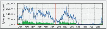
Figure 2. The statistics for network traffic between the Buarth and the Old College June 2003 – June 2004 (time runs right to left).
The equipment also generates statistics — via SNMP (Simple Network Management Protocol) — on the strength of the signal between the wireless bridges. This is given as a percentage of full strength. Experience has shown that even a figure between 30% and 50% provides a perfectly good service. An example of recent statistics for signal strength appears in Figure 1.
The wireless signal strength is stronger in dry, clear conditions and weaker in wet, windy, conditions. However, this has been found to have no adverse effect on the actual data throughput of the link. This is obviously a positive factor for those locations on the western shores of the British Isles, such as Aberystwyth.
Quality of Service at Layer 2 has been implemented for videoconferencing applications at UWA by the deployment of dedicated VLANs. However, the link is well provisioned and there has been no need to deploy any QoS measures. No voice or video applications are currently used over the link.
Benefits of Project
It is possible to see from the network traffic statistics (Figure 2) that the link has supported a steady growth in the volume of traffic between the Old College and the Buarth. It is possible to map traffic data using various sampling periods to provide averages, and the link has shown volume growth whatever the sampling period. As would be expected in an educational establishment, there are wide variations of traffic volume levels at different times of the day and night, and at different times of the year. On all measurements, however, there has been a volume increase. The link has not introduced any latency, and the traffic levels — while rising steadily — have stayed within its capacity.
There have been a number of unexpected benefits beyond the initial requirement of providing a better network quality of service to the Buarth:
- The 24 hour access public workstation room has increased in size from 10 workstations at the time of the project, to 15 at the time of writing. It was also moved to a new location to accommodate this growth.
- The University uses Citrix® thin clients where appropriate for some public and post-graduate student PCs. The servers are on the main campus, separated from the Buarth machine clients by the Infrared link to the Old College and the Aironet® wireless link to the Buarth itself. The previous link did not support this type of use, as there was simply too much congestion, and thus, latency over the link. However, approximately half a dozen Citrix® client machines are now in regular use at the Buarth, a year after the installation of the Aironet link. So the improved link helps provide a service which was not possible previously — and the Citrix® clients continue to give good performance.
- The University has a policy of connecting all student halls of residence to allow students network access from within their own rooms. The link from the Buarth to the Old College has enabled the connection of a student hall of Residence housing more then one hundred students. The additional traffic that could be generated by the addition of this number of student machines with unfettered access could cause congestion at the core of the network, or the site access router. For this reason, this traffic is routed via a layer 3 router which shapes (or ‘throttles’) the traffic to the Old College and the Buarth during the day. The traffic coming INTO the network is far greater and therefore more threatening to susceptible network links than that generated and sent OUT OF the network by the students. For this reason all inboundThe Cisco® 3500 and Air1-arts are in the Old College, the Cisco® 1950 switch and Air2-arts are in the Buarth. Incoming traffic bound for a student destination is forced to the student router, smoothed, and then sent back to the main campus switch. The student router connection is a single physical connection, but is shown here as two logical connections, over two different VLANs that are trunked together down a single physical link. The wireless solution chosen needed to support this VLAN deployment.
- Performance has been so good that it is likely the Aironet® wireless link will be doubled up during summer 2004. The link will then run with two base stations in parallel, doubling up the available bandwidth to 11Mbit/s. An alternative still under consideration is to replace the 802.11b link with an 802.11g link, allowing a nominal 54Mbit/s bandwidth between the two sites involved. If the latter were implemented it would be possible to use Cisco® equipment again and also re-use the current antennas, thus saving on the total cost of the package.
Lessons Learned
It is difficult to draw anything but positive lessons from this project. The installation of an 802.11b wireless solution for connecting two buildings with line of sight proved to be a simple, efficient, economical, robust and reliable means of solving inter-building connectivity at high-bandwidth. Since this original project, the team has installed further wireless solutions based on the Cisco® Aironet® equipment. It is worth mentioning that the same equipment can also be used as an 802.11b wireless access point.
The project came in on budget, and on time. This is a solution that any network engineer with Cisco® competence should consider as an alternative to leased lines or LES circuits. traffic for the School of Art is first directed through the router – which ‘smoothes’ it– before being sent down to the Old College (see Figure 3).
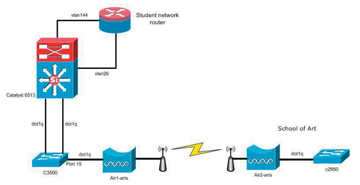
Figure 3. Wireless Link to the School of Art Building
Summary
This project had a simple aim: to replace a failing network link between two buildings that were about 800 metres apart. The replacement needed to offer better bandwidth than the existing (clogged) 2Mbit/s link. It had to be simple to set up and maintain. It could not involve external aerials or antennas on either building. If competing solutions emerged from these requirements then the selection was to be made based on cost. The total cost should be— ideally — not over £5,000.
802.11b technology virtually chose itself as the only option that met all of the criteria. One alternative was Infrared (or ‘laser’) links, but this was rejected because the link could not perform adequately behind the heavily leaded windows of the Buarth, which as a listed building could not have an externally mounted aerial. Another alternative was a BT LES-10 circuit, but the cost of this was considerably higher than that of the wireless solution. An opportunity to loan Cisco® 802.11b equipment demonstrated that the technology was reliable as well as being not difficult to implement and configure for anyone with reasonable knowledge of Cisco® configuration. Other manufacturers’ 802.11b solutions were surveyed, but none of these offered the support for 802.1q VLANs which was essential for integration with the existing UWA network.
The solution finally adopted was a pair of Cisco® Aironet® 350s with a Yagi antenna attached to each. These were set up on the workbench to test performance and configuration, and were then moved to their final location. Once in place the only further configuration necessary was to tune the signal strength (aided by software supplied for the purpose). The workbench tests were then repeated with only minor variation in the results. The entire project cost approximately £3,000 plus only a few days of UWA network team time. A laptop to allow remote management of the wireless bridges, which was also capable of generating heavy bi-directional traffic, was an essential tool for this job.
The wireless link has now been in place for two years, has worked well and has been extremely low maintenance. It has seen a steady rise in the amount of traffic, and has supported additional — unforeseen — network expansion. Similar solutions have been implemented elsewhere at the University following the experience gained from this project. For institutions that wish to link two buildings at 5Mbit/s+ simply, cheaply and reliably, an 802.11b wireless bridge solution is heartily recommended.
References
Cisco® Aironet® documentation: http://www.cisco.com/en/US/products/hw/wireless/ps458/index.html
BT LES-10 Circuits: http://www.serviceview.bt.com/list/current/docs/Private_Cir_.boo/130999.htm
Infrared (or ‘laser’) solution: http://www.cablefreesolutions.com/cfproductsaccess.htm
IEEE 802 Standards Home Page: http://www.ieee802.org/
JANET® Wireless Technology Advisory Service: https://community.ja.net/library/advisory-services/wireless-technology-advisory-servicel
Appendix 1: Photographs showing the buildings involved in the link.
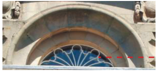
1. The selected window at the Buarth with the Cisco® Yagi antenna visible on the right.

2. The front of the Buarth. The antenna is in the semi-circular attic window above the main entrance.

3. The front of the Buarth.
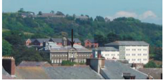
4. The Buarth seen from the roof of the Old College, taken from near the Cisco® Yagi antenna. An arrow indicates the window in pictures 1-3.

8. The Old College seen from a point close to the wireless installation at the Buarth. An arrow indicates the location of the antenna at the Old College.

9. The Cisco Yagi antennae in position at the Old College.

10. The Aironet 350 wireless bridge in position at the Old College.

11. Looking down the Cisco Yagi antennae at the Buarth building across the town.
Trademarks:
Cisco® is a registered trademark of Cisco Systems, Inc. and/or its affiliates in the US and certain other countries.
Aironet® is a registered trademark of Cisco Systems, Inc. and/or its affiliates in the US and certain other countries.
Citrix® referenced herein is a registered trademark of Citrix Systems, Inc. in the United States and other jurisdictions.


